ToslinkCNC - release
ToslinkCNC is our answer to grounding and interference issues commonly experienced with DIY and low-cost CNC machines. Instead of investing in shielding opto-couplers, we have used low-cost fibre optic cables to change the wiring approach on CNC machines. Stepper motor and driver are placed closely together, preferably in a shielded box, and receive only stabilized DC input and command signals via the optic cable. The controller itself is placed safely away from the machine and thus completely decoupled. The ToslinkCNC transceiver board co-located with the stepper and driver provides step, direction and enable signals as well as an opto-coupled input for a limit switch and an output for enabling peripherals. ToslinkCNC transceiver boards can be daisy-chained to minimize optical wiring required.
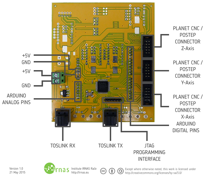
Prototypes tested on GoodenoughCNC Plasma cutter were finalized and operate in the following manner: ToslinkCNC Transmitter consists of an universal PCB, which can be used as an Arduino Uno shield or connected to an external CNC controller, such as PlanetCNC, via screw terminals or IDC connectors. The alternative use of this board is a a multi-axis receiver for use in scenarios where optical isolation is required between controller and co-located drivers. Additionally there are sockets for step-stick Pololu’s DRV8825 drivers on the shield itself.
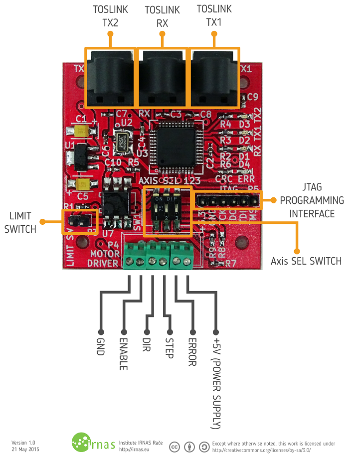
ToslinkCNC transceiver is a single axis (selectable via DIP switch) device to be placed next to a motor driver, either PoStep25-32 or any other accepting step/direction/enable signals. The optical input is connected via the on-board CPLD to two transmitters, such that drivers can either be connected in a daisy-chain or tree configuration. The driver replaces the bit controlling the digital output with the state of its digital input, allowing this to be used either to carry the limit switch back to the controller or to send a digital signal between two transceiver boards. The dual-output feature also enables unlimited axis signal cloning, as we can have a number of transceiver boards in a chain and configured to receive signals of the same axis.
The back-end of this system is Xilinx XC9572XL CPLD implementing Manchester encoded signal in sequential packets carrying step, direction, limit switch signal for three axis and a general enable signal. A special mechanism is put in place to ensure step and direction signals are correctly synchronised and avoid potential issues.
Alternative uses of this hardware configuration with firmware adaptation can be synchronising digital signals between two boards much like a multi-channel opto-coupler or for sending UART, I2C or SPI. With enough interest, we will look into this features.
An interesting hack is also using these transceivers with raw 1mm PMMA fibre without the use of Toslink cables with connectors, simply by drilling a hole through transmitter or receiver protective cap or even using the fibre and adding a few heat-shrink tubes on the end to hold it in place.


