Developing KORUZA Pro: Koruza Driver - Part 2
We’ve come a long way since our last blog post on Koruza real time (move) driver with many improvements made to the system, including the changes to the real-time driver itself. The new structure of electronics is much more fault tolerant because of the simplicity and task distribution. The Koruza move driver is now just a simple board dedicated to only one true real-time task - moving the stepper motors. Although the board has only few components, and one “simple” task, it is still one of the crucial parts of the system.
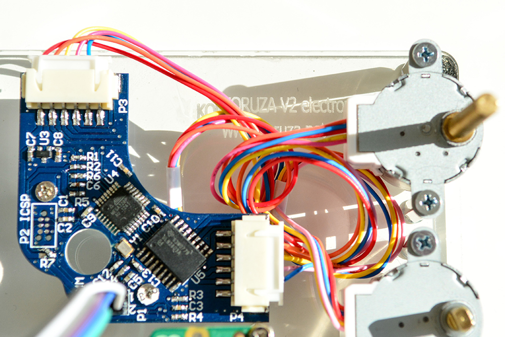
The main and only MCU on the board is the one and only ATmega328P, which is Arduino compatible. The MCU tasks are: driving the stepper motors, reading the switches and encoders, and communicating with the main board. For driving motors, there is one high-current Darlington transistor array. On the board back, at the end of the motor shafts two magnetic encoders are positioned. Two encoders are TLV493D from Infineon, the Arduino lib for it is available on GitHub as usual. Besides two motor connectors and one programming connector, used only for flashing the bootloader for the first time, there is another connector used for communication between the boards and for powering the driver board. It has standard UART RX/TX pins with an additional reset pin so firmware upgrades can be done “over the air”. Communication protocol stayed the same and typical input power is +9 V. Now, this board has a very interesting shape and it is a perfect fit for the inside of the KORUZA Pro unit, which you can see on the picture below.
Separating the motor driver was a good idea for lots of reasons with one of the main ones being that by doing this we have created a simple upgradeable structure that can be restarted at any time. To conclude, the process of developing Koruza driver is a good example of how keeping things simple results in much greater resistance to failure.


